How DAF System Equipment Improves Industrial Wastewater Clarity
How DAF System Equipment Improves Industrial Wastewater Clarity
September 30, 2026
Author
Solution Provider, through a professional technical team, we provide customers with targeted equipment selection recommendations and comprehensive after-sales services, winning the trust and recognition of customers.
Sarah M.
Dissolved air flotation (DAF) is one of the most effective technologies for improving industrial wastewater clarity, and this article explains why. Rather than relying on gravity to settle solids, DAF dissolves air in water under pressure and releases it as microscopic bubbles that attach to chemically destabilised particles, lifting them to the surface for removal by skimming. This buoyancy-driven mechanism makes DAF uniquely suited to the light, oily, fibrous, and colloidal contaminants that cause turbidity and that conventional clarifiers handle poorly. The article examines the underlying physics, including Henry's law, saturator operation, bubble size distribution, and particle-bubble attachment, before exploring the essential role of coagulation and flocculation chemistry. It describes the anatomy of a modern DAF system, from rapid mix and flocculation chambers through the air dissolution system, flotation tank, skimmer, and effluent collection. Key design parameters are reviewed in detail, including the air-to-solids ratio, recycle ratio, saturator pressure, hydraulic and solids loading rates, and retention times, with guidance on how each influences achievable clarity. Industry-specific sections cover food and beverage, meat and poultry, dairy, textiles, pulp and paper, petrochemicals, metal finishing, pharmaceuticals, automotive, mining, and laundries, showing how DAF performance is tailored to different contaminant profiles. The article also compares DAF with sedimentation, lamella clarifiers, ultrafiltration, membrane bioreactors, and centrifugation, and explains why DAF is such an effective pretreatment for membrane systems. Practical content includes a troubleshooting table for common clarity problems, maintenance practices that protect performance, commissioning guidance, and an economic overview covering energy, chemicals, and sludge handling. The article concludes by discussing how integrated suppliers — such as HINADA Water Treatment Tech Co., Ltd., a manufacturer of DAF systems, hollow fibre UF membranes, submerged MBR modules, and packaged treatment plants — help industrial facilities achieve reliable, sustainable clarity outcomes.
How DAF System Equipment Improves Industrial Wastewater Clarity
Industrial wastewater clarity is rarely an accident. It is the predictable outcome of well-chosen unit operations working in sequence, and among those unit operations, dissolved air flotation (DAF) has earned a reputation as one of the most dependable tools for turning murky, oily, solids-laden process water into a stream that downstream equipment, discharge permits, and reuse specifications can all accept. Where conventional gravity settling is slow, bulky, and easily upset by buoyant or near-neutral-density particles, a properly designed DAF system equipment package attacks the same problem from the opposite direction: instead of waiting for solids to sink, it attaches microscopic air bubbles to them and floats them to the surface, where they can be skimmed away in minutes rather than hours.
This article examines, in depth, the mechanisms by which dissolved air flotation improves industrial wastewater clarity. It explores the physics of bubble formation, the chemistry of coagulation and flocculation that makes those bubbles effective, the mechanical anatomy of a modern DAF unit, the design parameters that separate a high-performing installation from a marginal one, and the industry-specific considerations that determine whether a DAF system will deliver clear effluent year after year. It also reviews troubleshooting, economics, comparisons with competing clarification technologies, and the operational discipline required to keep clarity performance stable over the long run.
undefined
What Industrial Wastewater Clarity Actually Means
Clarity is a deceptively simple word for a multi-dimensional water quality objective. In practical engineering terms, clarity is the visible expression of several measurable parameters working together: total suspended solids (TSS), turbidity in nephelometric turbidity units (NTU), oil and grease concentration, colour, and the presence of colloidal material that scatters light. A wastewater stream can be low in TSS yet still appear cloudy because of fine colloids or emulsified oil. Conversely, a stream with visible settleable solids may report moderate turbidity if the particles are large and few in number. Understanding this distinction matters because DAF systems improve clarity through several distinct pathways, and the pathway that dominates depends on the nature of the contaminants present.
Turbidity is the parameter most closely associated with visual clarity. It measures the scattering of light by suspended and colloidal particles and is expressed in NTU or, in some jurisdictions, formazin turbidity units. Because light scattering is disproportionately influenced by particles in the size range of roughly 0.1 to 10 micrometres, turbidity is an excellent indicator of the fine colloidal fraction that gravity clarifiers handle poorly. This is precisely the fraction that dissolved air flotation excels at removing, which explains why DAF installations frequently deliver dramatic reductions in NTU even when the incoming TSS load is moderate.
Total suspended solids, by contrast, measure mass rather than optical effect. A DAF system may achieve ninety per cent TSS removal while only reducing turbidity by sixty per cent, or the reverse, depending on particle size distribution. Oil and grease, measured either gravimetrically or by infrared or solvent extraction methods, contributes to clarity problems in a different way: emulsified oil droplets scatter light, form stable films on equipment surfaces, and can blind downstream membranes. Colour, whether from dyes, lignin, humic substances, or metal complexes, may persist even after all suspended matter has been removed, and this is an important limitation to acknowledge when setting expectations for any clarification technology.
The practical implication is that clarity improvement must be engineered, not assumed. A DAF system is a powerful tool, but it works best when the contaminant profile is understood, the chemistry is matched to that profile, and the hydraulic and solids loading rates are chosen with the specific particle characteristics in mind. When those conditions are met, DAF routinely produces effluent with TSS below 30 milligrams per litre, turbidity below 10 NTU, and oil and grease below 10 milligrams per litre — figures that open the door to discharge, reuse, or membrane-based polishing.
The Science Behind Dissolved Air Flotation
To understand why DAF improves clarity so effectively, it helps to understand the physical and chemical principles on which it depends. Dissolved air flotation is not a filtration process, nor is it a settling process in the conventional sense. It is a buoyancy-driven separation process in which air, dissolved under pressure, is released as microscopic bubbles that attach to suspended particles and lift them to the surface.
Henry's Law and the Physics of Dissolved Air
The foundation of DAF is Henry's law, which states that the amount of gas that can be dissolved in a liquid at equilibrium is directly proportional to the partial pressure of that gas above the liquid. In a DAF system, a portion of clarified effluent — known as the recycle stream — is pumped into a pressure vessel called a saturator, where air is injected and held at pressures typically between 3 and 6 bar. Under these conditions, water can hold far more dissolved air than it can at atmospheric pressure. At 20 degrees Celsius and one atmosphere, water saturates at roughly 18.7 millilitres of air per litre. Raise the pressure to five atmospheres, and the saturation capacity increases roughly fivefold.
When this air-saturated recycle stream is returned to atmospheric pressure — usually by passing it through a specially designed needle valve or back-pressure regulator — the excess dissolved air comes out of solution. Because the pressure drop is sudden and the release point is engineered to promote nucleation, the result is a cloud of bubbles in the 20 to 100 micrometre range, with a significant population of bubbles between 30 and 50 micrometres. This bubble size distribution is critical: bubbles that are too large rise quickly but provide little surface area and shear flocs apart, while bubbles that are too small rise too slowly to be captured by the skimmer.
Bubble Formation: From Supersaturated Water to Micro-Bubbles
The efficiency with which dissolved air is converted into useful bubbles is quantified by the saturation efficiency, usually expressed as a fraction between 0.5 and 0.9. Several factors influence this value. The design of the saturator itself matters enormously: packed saturators filled with structured media provide large interfacial area and long contact time, achieving higher dissolution efficiency than unpacked vessels. The pressure at which the saturator operates sets the upper bound on dissolved air content. The temperature of the water affects solubility, since cold water dissolves more air than warm water. Finally, the design of the release valve determines how the pressure energy is dissipated and how nucleation sites are generated.
In practice, operators should expect bubble clouds to contain a distribution of sizes rather than a single uniform diameter. The smaller bubbles contribute to the formation of a stable float blanket at the surface, while the larger bubbles provide the buoyant lift needed to transport flocs upward. The balance between the two determines both the rise rate and the quality of the float layer that forms.
Particle-Bubble Attachment: The Heart of DAF Performance
Bubbles alone do not clarify water. They must attach to particles, and that attachment depends on a combination of collision, adhesion, and hydrodynamic forces. Collision frequency increases with bubble concentration and particle concentration, which is why higher air-to-solids ratios generally improve removal — up to a point. Adhesion depends on surface chemistry. Most suspended particles in industrial wastewater carry a negative surface charge, and so do air bubbles in water at neutral pH. Without intervention, electrostatic repulsion would prevent attachment entirely.
This is where coagulation and flocculation chemistry becomes indispensable. By adding coagulants such as aluminium or iron salts, or cationic polymers, the surface charge of the particles is neutralised and the electrostatic barrier is removed. Flocculant polymers then bind individual particles and small flocs into larger, more robust aggregates that can accommodate multiple bubbles. The resulting bubble-floc agglomerate has an effective density far lower than water, typically in the range of 0.05 to 0.3 grams per cubic centimetre, which produces rapid rise velocities and allows compact flotation tanks with short hydraulic retention times.
Where DAF Fits in the Industrial Wastewater Treatment Train
Dissolved air flotation is rarely a standalone solution. It occupies a specific and valuable position within a treatment train, and its clarity benefits are amplified when it is correctly integrated with upstream and downstream processes.
Primary Treatment Applications
In many industrial facilities, DAF serves as the primary clarification step, removing the bulk of suspended solids, fats, oils, and grease before biological treatment. This role is particularly important when the wastewater contains high concentrations of emulsified oil or light solids that would otherwise accumulate in biological reactors, smother biomass, or cause foam formation. By reducing the organic load entering the biological stage, DAF also reduces aeration demand and sludge production downstream.
Secondary and Tertiary Polishing
In other configurations, DAF acts as a polishing step following biological treatment, clarifying secondary effluent and removing residual suspended solids, algae, and phosphorus-bearing flocs. Tertiary DAF is widely used where discharge limits for total phosphorus or TSS are stringent, and it is a common pretreatment choice ahead of ultrafiltration and reverse osmosis membranes, since it protects membrane surfaces from fouling by particulate and oily matter.
Sludge Thickening
A third major application is sludge thickening. Dissolved air flotation thickeners concentrate waste activated sludge, chemical sludge, or mixed sludge from one to three per cent solids up to four to eight per cent, reducing the volume that must be dewatered and transported. This application uses the same physical principles but with a different design emphasis, prioritising float blanket stability and sludge concentration rather than effluent clarity. Even so, the quality of the subnatant liquor matters, because it is usually returned to the head of the plant and can impose a significant internal loading if not adequately clarified.
The Anatomy of a Modern DAF System
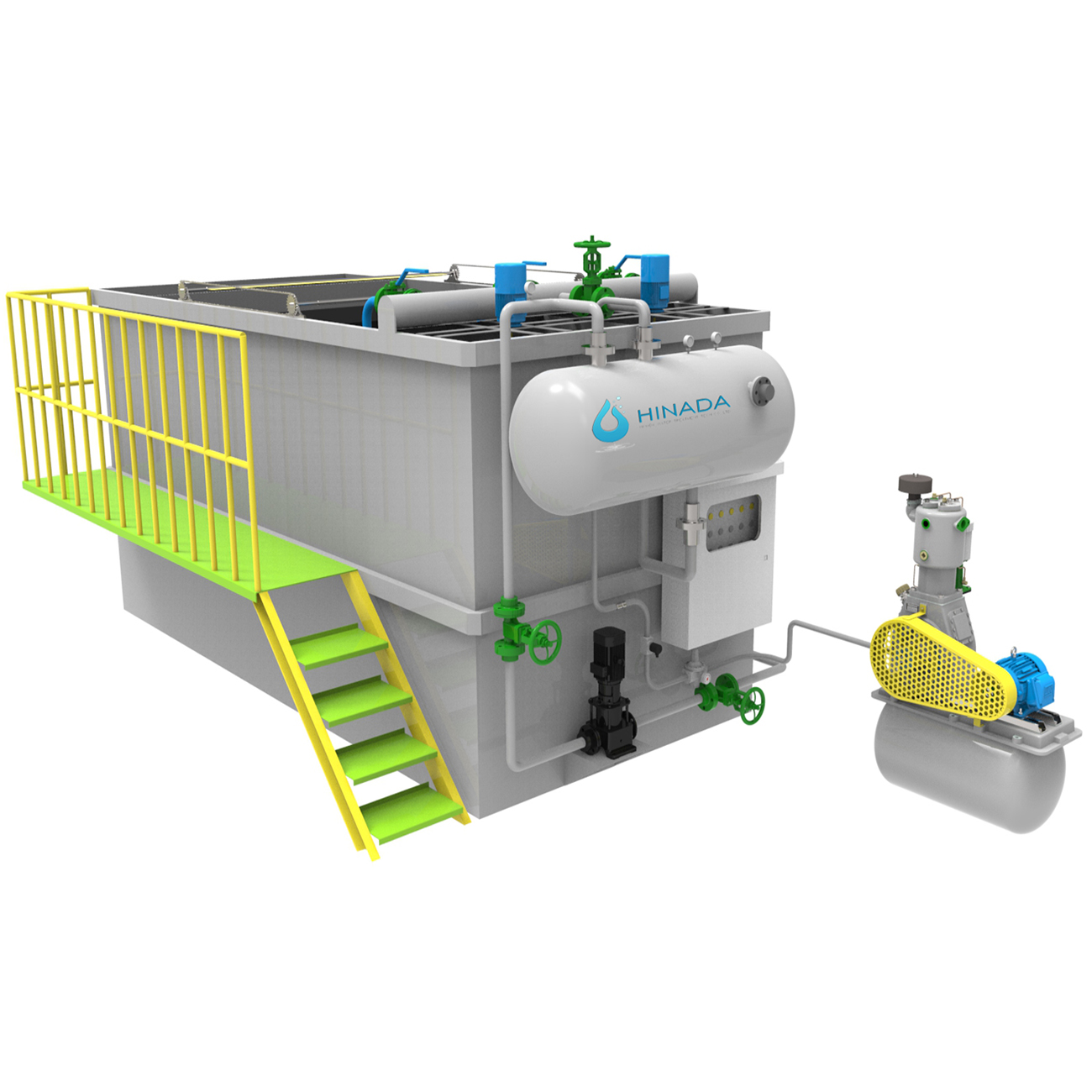
A modern DAF system equipment package is a carefully orchestrated assembly of hydraulic, chemical, mechanical, and control components. Each element contributes to the final clarity outcome, and a weakness in any one of them will show up as turbidity in the effluent.
Influent Pumping and Chemical Conditioning
Wastewater enters the system through a feed pump, often preceded by screening or grit removal to protect downstream components. Immediately after entering, coagulant is dosed and rapidly mixed. The rapid mix stage is deliberately turbulent, with velocity gradients typically between 300 and 1000 reciprocal seconds, to ensure that coagulant molecules contact particles within milliseconds. Insufficient mixing energy at this stage produces poor coagulation and, ultimately, poor clarity that no amount of downstream adjustment can repair.
Coagulation and Flocculation Chambers
Following rapid mix, the flow enters a slower flocculation zone where gentle agitation encourages particles to collide and aggregate. Velocity gradients here typically fall between 20 and 80 reciprocal seconds, and the flocculation time ranges from five to twenty minutes depending on the floc strength required. Flocculant polymer is usually added at the beginning of this stage, sometimes in two stages for difficult wastewaters. The design of the flocculation chamber — whether it uses mechanical paddles, hydraulic baffles, or a combination — strongly influences floc size distribution and the subsequent efficiency of bubble attachment.
The Air Dissolution System
The saturator and its associated recycle pump form the heart of the DAF process. Clarified effluent is drawn from the outlet end of the flotation tank, pressurised, and delivered to the saturator, where compressed air is introduced. The air-water mixture is held under pressure long enough for dissolution to approach equilibrium, then released into the flotation tank through a distribution manifold. The design of this manifold determines how evenly the bubble cloud is distributed across the tank cross-section, which in turn determines whether the float blanket forms uniformly or develops thin spots that allow solids to escape.
The Flotation Tank
The flotation tank is where separation occurs. Its geometry, depth, and internal baffling all influence performance. A typical tank provides a hydraulic retention time of twenty to forty minutes, with an effective depth of 1.5 to 3 metres. Some designs incorporate inclined plates or lamella packs to increase the effective settling and rising area, allowing higher loading rates and smaller footprints. Inlet arrangements are designed to dissipate energy gently so that incoming flocs are not sheared apart, and outlet arrangements are designed to collect clarified water without drawing down the float blanket.
The Surface Skimmer and Sludge Collection
Floated material accumulates at the surface as a blanket of sludge that is typically three to fifteen centimetres thick. A mechanical skimmer — either a chain-and-flight system, a travelling scraper, or a rotating scoop — continuously removes this material into a sludge hopper or trough. Skimmer speed and frequency are important operating variables. Too slow, and the blanket thickens to the point where it becomes unstable and begins to sink. Too fast, and dilute sludge is produced that is difficult to dewater and increases downstream costs.
Effluent Collection and Discharge
Clarified effluent is collected through submerged pipes or adjustable weirs positioned below the float layer. The collection system must be designed to draw water evenly across the tank width; uneven collection creates short-circuiting, dead zones, and localised high-velocity zones that entrain solids. Adjustable weirs allow operators to compensate for changes in flow rate and to fine-tune the water level relative to the skimmer.
Instrumentation and Control
Modern DAF systems increasingly incorporate instrumentation for flow, turbidity, pH, and suspended solids, together with programmable logic controllers that adjust chemical dosing and recycle rates automatically. Real-time turbidity monitoring on the outlet provides immediate feedback on performance and allows early detection of upsets. Automatic control of coagulant and polymer dosing based on influent characteristics reduces chemical consumption while maintaining clarity — a benefit that pays for the instrumentation within a short period in most installations.
Coagulation and Flocculation Chemistry: The Invisible Partner
No discussion of DAF clarity performance is complete without acknowledging that chemistry does much of the work. The physical process of flotation is only as effective as the flocs it is asked to float.
Inorganic coagulants such as aluminium sulphate, polyaluminium chloride, ferric chloride, and ferrous sulphate are widely used because they hydrolyse rapidly, form positively charged species that neutralise negative particle surfaces, and produce hydroxide flocs that enmesh fine particles. The choice between them depends on pH, alkalinity, temperature, and the nature of the contaminants. Polyaluminium chloride, for example, performs well over a broader pH range and produces less sludge than aluminium sulphate, while ferric salts are often preferred for colour removal and for wastewaters containing sulphides.
Organic polymers serve two distinct functions. Cationic coagulants, usually low to medium molecular weight, act primarily through charge neutralisation and can replace or supplement inorganic coagulants. High molecular weight anionic or cationic flocculants bridge particles together into large, loosely bound aggregates that are ideal for bubble attachment. Overdosing flocculant is a common mistake: excess polymer can re-stabilise particles, increase viscosity, and produce a sticky float that is difficult to skim. Jar testing remains the most reliable way to establish the correct dose, and it should be repeated whenever the wastewater characteristics change.
pH control is frequently overlooked but rarely unimportant. Most coagulants have a narrow optimal pH window, typically between 5.5 and 7.5 for aluminium salts and between 4.5 and 6.5 for iron salts in certain applications. Outside that window, hydrolysis products are ineffective and residual metal concentrations rise. For wastewaters with high buffering capacity, acid or alkali dosing may be required, and the cost of that dosing must be factored into operating budgets.
How DAF Actually Improves Clarity: The Mechanisms Explained
The clarity improvements delivered by dissolved air flotation can be attributed to several distinct mechanisms, each operating on a different fraction of the contaminant load.
Physical attachment and buoyant lift — micro-bubbles attach to flocculated particles and carry them to the surface, removing them from the bulk liquid.
Entrainment in the rising bubble cloud — particles that do not attach directly are swept upward by the hydrodynamic drag of the rising bubble swarm.
Blanket filtration — as the float layer thickens, it acts as a coarse filter that intercepts additional particles carried upward by the flow.
Coagulation and charge neutralisation — chemical pretreatment destabilises colloids, allowing them to aggregate into particles large enough to be floated.
Oil droplet coalescence — emulsified oil droplets, destabilised by coagulants, coalesce at bubble surfaces and rise with the float.
Adsorption onto floc surfaces — dissolved and colloidal colour bodies adsorb onto hydroxide flocs and are removed with them.
Gas stripping of volatiles — the large volume of air introduced into the system strips some volatile organic compounds and odorous substances.
Removal of Suspended Solids
Suspended solids removal is the primary clarity benefit of DAF. Typical removal efficiencies range from 85 to 98 per cent for well-designed systems treating chemically conditioned wastewater. The removal efficiency depends strongly on the ratio of air to solids, the quality of floc formation, and the hydraulic loading rate. When these are properly balanced, effluent TSS values of 10 to 30 milligrams per litre are routinely achievable, and values below 10 milligrams per litre are possible with optimised chemistry and low loading rates.
Removal of Oils and Greases
Free and emulsified oils are particularly well suited to flotation because their density is already lower than water. Emulsified oils, however, require chemical demulsification before they can be floated effectively. Once the emulsion is broken, oil droplets coalesce and rise, either on their own or attached to bubbles. Removal efficiencies above 90 per cent are common in well-designed systems treating metalworking fluids, food processing waste, and refinery streams. Residual oil concentrations below 10 milligrams per litre are achievable, and this is often the threshold required for membrane pretreatment.
Removal of Colour and Colloidal Matter
Colour removal by DAF depends on the ability of coagulants to adsorb colour bodies onto hydroxide flocs. This works well for colloidal and particulate colour, such as that from textile dyes bound to clay particles or from paper mill fines. It works less well for dissolved colour, which requires oxidation, adsorption onto activated carbon, or membrane treatment. A realistic expectation is that DAF will remove a substantial portion of apparent colour associated with suspended and colloidal matter, while dissolved colour may require additional treatment.
Reduction of Turbidity
Turbidity reduction follows directly from the removal of fine particles and colloids. Because turbidity is dominated by particles in the sub-ten-micrometre range, and because those are exactly the particles that respond best to coagulation followed by flotation, DAF is often more effective at reducing turbidity than at reducing mass-based TSS. Reductions of 80 to 95 per cent in NTU are typical, with final values frequently in the range of 3 to 15 NTU depending on the influent characteristics and the treatment objectives.
Secondary Benefits for Downstream Processes
Beyond the visible improvement in clarity, DAF delivers secondary benefits that ripple through the entire treatment train. By removing fats, oils, and grease, it prevents the formation of foam and scum in biological reactors. By reducing suspended solids, it lowers the organic load expressed as biochemical oxygen demand and chemical oxygen demand, often by 30 to 60 per cent for particulate-associated BOD and COD. By removing a significant fraction of bacteria and other pathogens attached to particles, it improves the performance of downstream disinfection. And by clarifying the water before membrane filtration, it dramatically reduces fouling rates and extends cleaning intervals.
Types of DAF Systems and Their Clarity Characteristics
Not all DAF systems are alike. The choice of configuration has a direct effect on achievable clarity, footprint, and operating cost.
Circular or Vertical DAF Units
Circular DAF units, also called vertical units, use a cylindrical tank with a rotating scraper mechanism that sweeps floated sludge into a central or peripheral hopper. They are compact, well suited to smaller flows, and relatively easy to cover for odour control. Their hydraulic characteristics are generally good, but they can be sensitive to sudden flow surges, and the rotating mechanism requires regular maintenance. They are common in food processing, small industrial facilities, and packaged treatment plants.
Rectangular or Horizontal DAF Units
Rectangular units use a long, shallow tank with a chain-and-flight skimmer that moves floated sludge to one end. They are the workhorse configuration for medium to large industrial flows, offering excellent hydraulic stability, easy access for maintenance, and the ability to handle high solids loads. Their footprint is larger than circular units for the same capacity, but their process stability and predictable performance make them the preferred choice where clarity targets are stringent.
Plate-Pack and Lamella DAF Units
Inclined plate packs installed within the flotation tank increase the effective separation area, allowing higher hydraulic loading rates and smaller tank volumes. The plates also promote the coalescence of bubbles and flocs, which can improve effluent quality for certain wastewaters. The trade-off is a greater risk of plate fouling and a more demanding cleaning regime, particularly when the wastewater contains high concentrations of oil or fibrous material.
High-Rate DAF Units
High-rate DAF systems employ optimised inlet geometry, high recycle ratios, and sometimes inclined plates to achieve hydraulic loading rates of 15 to 30 metres per hour, compared with 4 to 10 metres per hour for conventional units. They are attractive where space is limited, but they demand excellent upstream coagulation chemistry and careful control of flow variations. When operated correctly, high-rate units can match conventional DAF clarity performance; when operated poorly, they produce turbid effluent and unstable float blankets.
Cavitation and Other Variants
Several alternative flotation technologies exist, including cavitation air flotation, in which a rotating impeller draws air into the water and generates bubbles mechanically, and induced gas flotation, widely used in the oil and gas industry. These variants differ in bubble size distribution and energy consumption, and they generally produce somewhat larger bubbles than dissolved air systems. For the most demanding clarity requirements, particularly where fine colloidal matter dominates, dissolved air flotation remains the benchmark technology.
Key Design Parameters That Determine Clarity Outcomes
The performance of a DAF system can be predicted, to a first approximation, from a small number of design parameters. Getting these right at the design stage is far less expensive than correcting them after commissioning.
Parameter
Typical Range
Effect on Clarity
Air-to-solids ratio (A/S)
0.02 – 0.10 by mass
Higher ratios improve removal up to an optimum; excessive air can destabilise the float
Recycle ratio
20 – 100 per cent of influent
Sets the volume of pressurised water available for bubble generation
Saturator pressure
3 – 6 bar
Higher pressure increases dissolved air and bubble density
Hydraulic loading rate
4 – 12 m/h conventional; 15 – 30 m/h high rate
Higher rates reduce tank size but increase risk of solids carryover
Solids loading rate
2 – 10 kg/m²·h
Overloading causes blanket instability and turbid effluent
Rise rate of bubble-floc agglomerates
5 – 20 m/h
Must exceed the downward flow velocity in the separation zone
Flotation tank retention time
20 – 40 minutes
Shorter times save space but reduce blanket consolidation
Flocculation time
5 – 20 minutes
Determines floc size and strength before bubble contact
Rapid mix velocity gradient
300 – 1000 s⁻¹
Insufficient mixing causes poor coagulation and persistent turbidity
Flocculation velocity gradient
20 – 80 s⁻¹
Too high shears flocs; too low produces weak, diffuse aggregates
The air-to-solids ratio deserves special attention because it links the physical and chemical aspects of the process. It is conventionally estimated using an equation that combines the air solubility at the operating temperature, the fraction of saturation achieved, the absolute saturator pressure, the recycle flow rate, the influent flow rate, and the influent suspended solids concentration. When the calculated ratio falls below the recommended range for the application, removal efficiency declines and effluent turbidity rises. When it substantially exceeds the recommended range, the excess air can create turbulence that disrupts the float blanket and produces a wet, unstable sludge.
Recycle ratio and saturator pressure are the two levers available to adjust the air-to-solids ratio during operation. Increasing recycle flow is generally more energy-efficient than increasing pressure, because pumping energy scales with flow while compression energy scales with pressure. However, high recycle ratios increase the hydraulic loading on the flotation tank, which can offset the benefits of additional air. The optimum combination is determined by the specific wastewater and must be validated during commissioning.
Industry by Industry: How DAF Improves Clarity Across Sectors
The versatility of dissolved air flotation is best appreciated by examining how it performs in different industrial contexts. Each sector presents a distinctive contaminant profile, and each requires a tailored approach.
Food and Beverage Processing
Food processing wastewater typically contains high concentrations of fats, oils, grease, suspended solids, and soluble organics. DAF is almost universally employed as the primary treatment step in this sector because it efficiently removes the floatable fraction that would otherwise overload biological treatment. Effluent clarity improvements are dramatic: influent TSS of 1000 to 3000 milligrams per litre is commonly reduced to below 50 milligrams per litre, and oil and grease concentrations fall from several hundred milligrams per litre to below 20. The recovered sludge, rich in fats and proteins, is often suitable for composting or anaerobic digestion, giving the process an economic dimension beyond compliance.
Meat, Poultry, and Rendering
Meat processing generates wastewater with very high loads of blood, fat, and proteinaceous solids. Blood in particular is difficult to treat because it is partly soluble and creates intense colour and turbidity. Effective DAF treatment in this sector requires robust coagulation with iron or aluminium salts, followed by polymer flocculation to build dense, buoyant flocs. Well-operated systems achieve TSS reductions above 90 per cent and substantial colour reduction, though residual soluble colour may persist and require polishing.
Dairy Processing
Dairy wastewater presents the challenge of highly emulsified fats together with dissolved lactose and proteins. The emulsification means that simple flotation is insufficient; chemical demulsification is essential. Once the emulsion is broken, DAF removes the liberated fat with high efficiency, and the resulting clarity improvement protects downstream biological treatment from shock loads and reduces the risk of foaming in aeration basins.
Textile and Dyeing
Textile effluent is characterised by intense colour, high suspended solids, and variable pH. DAF, combined with appropriate coagulant selection, removes the colloidal and particulate fraction of the colour load and clarifies the water substantially. For reactive dyes that remain dissolved, DAF serves as a pretreatment ahead of more advanced processes such as ozonation, activated carbon adsorption, or membrane filtration. In many mills, the clarity achieved by DAF is sufficient for discharge to municipal sewers, while reuse applications require further treatment.
Pulp and Paper
Paper mill effluent contains fibres, fillers, lignin derivatives, and resin acids. DAF is widely used both for process water clarification — allowing fibre recovery and reuse — and for effluent treatment. The clarity benefits extend beyond aesthetics: removing suspended solids from process water reduces deposits on paper machines, improves sheet quality, and lowers freshwater consumption.
Petrochemical and Refinery
Refinery wastewater contains free and emulsified oil, phenols, sulphides, and suspended solids. DAF, often in the form of induced gas flotation for safety reasons, removes the bulk of the oil load and produces a clarified stream suitable for biological treatment. The clarity achieved is critical because residual oil can inhibit nitrifying bacteria and cause biomass flotation in secondary clarifiers.
Metal Finishing and Electroplating
Metal finishing wastewater is treated by chemical precipitation of dissolved metals, followed by separation of the resulting hydroxide flocs. These flocs are light, gelatinous, and slow to settle, making them ideal candidates for flotation. DAF removes the flocs rapidly and produces a clarified effluent with low residual metal concentrations, while the sludge is thickened to a manageable concentration for dewatering. Clarifying rinse water in this way also supports recycling within the plant.
Pharmaceutical and Chemical Manufacturing
Pharmaceutical and specialty chemical plants generate wastewaters that vary widely in composition, often containing solvents, surfactants, and fine particulate matter. DAF provides robust clarification and, importantly, can be configured with closed covers and vapour extraction for odour and volatile organic compound control. The clarity improvement supports subsequent treatment by membrane bioreactors or activated carbon, both of which are sensitive to particulate loading.
Automotive and Parts Washing
Parts washing and paint booth wastewater contains detergents, oils, and paint solids. DAF clarifies these streams effectively, and the treated water is frequently recycled back to the washing process, reducing both freshwater consumption and discharge volumes. The clarity of the recycled water directly affects cleaning quality, which makes effective DAF performance a production concern rather than merely an environmental one.
Mining and Mineral Processing
Mining operations use DAF for clarification of process water and for treatment of tailings water, particularly where fine clay particles and residual reagents create persistent turbidity. The ability of DAF to handle fine, slow-settling particles gives it an advantage over conventional thickeners in these applications, and the clarified water is often suitable for reuse in the milling circuit.
Laundries and Vehicle Washing
Commercial laundries and vehicle wash facilities produce wastewater laden with detergents, oils, and lint. DAF removes the bulk of these contaminants and clarifies the water sufficiently for reuse in pre-wash stages. The compact footprint of packaged DAF units makes them particularly suitable for these relatively small but numerous discharge sources.
Measuring Clarity: The Instruments and Methods That Matter
You cannot manage what you do not measure, and clarity is no exception. A well-run DAF installation incorporates a monitoring programme that tracks performance at multiple points.
Online turbidimeters installed on the effluent line provide continuous feedback and are the most practical tool for detecting upsets. A sudden rise in turbidity may indicate a coagulant dosing failure, a flow surge, a recycle pump failure, or a change in influent characteristics. Combining online turbidity with periodic grab sampling for TSS, oil and grease, and chemical oxygen demand gives a complete picture.Float blanket depth is another valuable operational measurement. It can be assessed visually, or with ultrasonic or optical sensors in automated installations. Blanket depth that is too thin indicates under-skimming and loss of solids; blanket depth that is too thick indicates over-skimming or an overloaded system. The relationship between blanket depth and skimmer frequency should be established during commissioning and revisited whenever the wastewater changes.
Finally, dissolved air measurement — either by monitoring saturator performance or by measuring dissolved oxygen in the recycle stream — provides an early warning of saturator fouling or air injection problems. A saturator that is not achieving design saturation will produce fewer bubbles, and the first symptom is a gradual deterioration in effluent clarity.
Designing for Clarity: Practical Engineering Considerations
Sizing the Flotation Tank
Tank sizing must satisfy two constraints simultaneously: the hydraulic loading rate and the solids loading rate. Designing to meet only one of these is a common error. A tank sized for hydraulic loading alone may be overwhelmed when solids concentrations spike, while a tank sized for solids loading alone may be unnecessarily large during low-solids periods. The design should be based on the more demanding of the two, with a margin for variability.
Recycle Ratio and Saturator Pressure
The recycle system should be designed with variable-speed control so that the air-to-solids ratio can be adjusted as influent conditions change. A fixed-speed recycle pump forces operators to choose a single operating point that is rarely optimal across the full range of conditions. Saturator pressure should be set high enough to achieve the target air-to-solids ratio but not so high that energy costs become excessive; in most cases, four to five bar represents a sensible compromise.
Chemical Programme Selection
Chemical selection should be based on jar testing with the actual wastewater, not on general rules of thumb. Jar tests should evaluate coagulant type and dose, pH adjustment requirements, flocculant type and dose, mixing intensity, and settling or flotation behaviour. Ideally, the jar test should include a flotation step, since flotation performance does not always correlate with settling performance. Once the programme is established, it should be reviewed regularly as production processes and raw materials change.
Temperature Effects
Temperature influences DAF performance in several ways. Cold water holds more dissolved air, which is beneficial, but it also has higher viscosity, which slows bubble rise and can reduce removal efficiency. Warm water reduces air solubility and can destabilise emulsions, changing the chemical demand. Seasonal temperature variation should therefore be considered during design, and the chemical programme may need adjustment between summer and winter.
Sludge Handling
The float sludge produced by DAF typically contains two to five per cent dry solids, depending on the application. Its handling must be considered during design: pumping characteristics, storage capacity, and dewatering method all affect the overall viability of the system. Thickening the float to a higher solids concentration reduces haulage costs but requires longer blanket retention times and careful skimmer control.
Common Operational Problems That Reduce Clarity — and How to Fix Them
Even well-designed DAF systems experience occasional clarity problems. Most can be traced to a small number of root causes, and a systematic troubleshooting approach resolves them quickly.
Symptom
Likely Cause
Corrective Action
High effluent turbidity with poor float formation
Insufficient coagulant or incorrect pH
Verify dose with jar tests; adjust pH to the coagulant optimum
Fine bubbles not attaching to flocs
Overdosed flocculant re-stabilising particles
Reduce polymer dose; switch to a different polymer chemistry
Float blanket breaking up and sinking
Excessive air-to-solids ratio or high turbulence
Reduce recycle ratio or saturator pressure; check inlet energy dissipation
Solids carryover at high flow
Hydraulic overload or short-circuiting
Equalise flow; inspect baffles and outlet collection for damage
Gradual decline in clarity over weeks
Saturator fouling or recycle pump wear
Inspect and clean saturator packing; verify recycle flow rate
Wet, dilute float sludge
Over-skimming or insufficient blanket consolidation
Reduce skimmer frequency; increase blanket retention time
Persistent colour despite low turbidity
Dissolved colour bodies
Consider oxidation, adsorption, or membrane polishing
Oil sheen on effluent
Incomplete demulsification
Adjust coagulant type or dose; consider pH adjustment or heat
Two operational habits prevent a large share of these problems. The first is regular jar testing, which detects changes in wastewater characteristics before they cause a plant upset. The second is disciplined record-keeping, which allows operators to correlate performance changes with process events upstream. In practice, most clarity failures are not failures of the DAF technology itself but of the monitoring and response system surrounding it.
Energy, Chemicals, and Footprint: The Economics of DAF Clarity
The cost of achieving clarity with DAF has three main components: energy, chemicals, and sludge management. Energy consumption is dominated by the recycle pump and the air compressor, with additional demand from skimmer drives and feed pumps. Typical specific energy consumption ranges from 0.1 to 0.4 kilowatt-hours per cubic metre of treated water, depending on the recycle ratio and saturator pressure.
Chemical costs often exceed energy costs, particularly for wastewaters requiring high coagulant doses. This is why optimising the chemical programme is the single most effective way to reduce operating costs without sacrificing clarity. Automated dosing based on online turbidity or flow-proportional control typically reduces chemical consumption by ten to thirty per cent compared with manual dosing.
Sludge management costs depend on the volume and concentration of the float. DAF produces a relatively concentrated sludge compared with conventional sedimentation, which reduces the volume that must be dewatered. However, the sludge often contains chemical precipitates and polymers that can affect dewaterability, and this should be evaluated during design.
Footprint is a frequently underestimated advantage of DAF. Because separation occurs at rise rates far higher than settling rates, a DAF tank occupies a fraction of the area required for a conventional clarifier of equivalent capacity. For industrial facilities with limited space, this can be decisive, and it is one reason why DAF is often chosen for retrofit projects where a new clarifier would simply not fit.
DAF Versus Alternative Clarification Technologies
Choosing the right clarification technology requires an honest comparison of strengths and limitations.
Technology
Typical Effluent TSS
Footprint
Best Suited To
Conventional sedimentation
40 – 100 mg/L
Large
Dense, fast-settling solids; large flows with available land
Dissolved air flotation
10 – 30 mg/L
Moderate
Light, buoyant, oily, or colloidal solids; space-constrained sites
Lamella clarifier
20 – 60 mg/L
Moderate
Moderate solids loads where settling is viable
Ultrafiltration membranes
Below 1 mg/L
Compact
High-quality reuse; requires pretreatment
Membrane bioreactor
Below 5 mg/L
Moderate
Combined biological treatment and clarification
Centrifugation
20 – 80 mg/L
Compact
Sludge dewatering rather than bulk clarification
The comparison reveals a clear pattern. Where solids are dense and settle readily, sedimentation remains the simplest and cheapest option. Where solids are light, oily, fibrous, or colloidal — or where space is limited — flotation offers decisive advantages. Where the highest possible clarity is required, membrane filtration is the benchmark, but it depends on effective pretreatment to control fouling. This is why DAF and membranes are so often paired.
Integration With Membrane Systems: DAF as the Ideal Pretreatment
The combination of dissolved air flotation followed by ultrafiltration or reverse osmosis has become a standard architecture for industrial water reuse. DAF removes the bulk of the suspended solids, oil, and colloidal matter that would otherwise foul membranes, while the membrane step removes the remaining fine particulates, macromolecules, and dissolved contaminants that DAF cannot address.
The benefits of this pairing are substantial. Membrane fouling rates drop significantly when the feed turbidity is low and stable, which extends cleaning intervals, reduces chemical cleaning costs, and prolongs membrane life. The DAF step also protects membranes from oil contamination, which is particularly damaging because oils can adsorb irreversibly onto membrane surfaces and are difficult to remove by conventional cleaning.
Manufacturers such as HINADA Water Treatment Tech Co., Ltd. supply both sides of this architecture. The company manufactures PVDF and PVC hollow fibre ultrafiltration membranes, submerged MBR membrane modules, containerised MBR systems, packaged wastewater treatment plants, ultrafiltration systems, industrial reverse osmosis systems, and dissolved air flotation systems. Founded in 2012 in Guangzhou, China, and later expanding its manufacturing base to Chenzhou in Hunan Province, HINADA serves clients in more than 75 countries across Asia, Africa, Europe, and the Americas. Because the same organisation supplies both flotation and membrane equipment, the interfaces between the two processes can be designed as a coherent system rather than assembled from unrelated components.
This systems approach matters more than it might appear. The optimum DAF effluent quality for a downstream membrane is not necessarily the same as the optimum for discharge. Membrane feed specifications may call for tighter limits on oil and grease than discharge permits require, and the DAF design must be adjusted accordingly. When a single supplier understands both the pretreatment and the membrane requirements, these interactions can be resolved at the design stage rather than discovered during operation.
Regulatory and Sustainability Drivers for Better Clarity
The push for improved wastewater clarity is not driven by aesthetics alone. Regulatory frameworks around the world increasingly impose limits on suspended solids, turbidity, oil and grease, and phosphorus, and these limits are tightening as receiving water bodies come under greater pressure. In many jurisdictions, discharge permits now specify turbidity limits in addition to mass-based TSS limits, precisely because turbidity better captures the fine colloidal fraction that harms aquatic ecosystems.
Beyond compliance, sustainability commitments are driving industrial facilities to adopt water reuse targets. Reuse requires clarity, often to a much higher standard than discharge. Cooling tower makeup, boiler feed, process rinse water, and irrigation all impose specifications on suspended solids and turbidity that demand effective clarification. DAF, particularly when combined with membrane polishing, provides a pathway to those specifications at a fraction of the cost of treating freshwater to the same standard.
There is also a growing recognition that clarity improvement supports resource recovery. The solids removed by DAF are not simply waste; they may contain fats suitable for biogas production, fibres suitable for recycling, or metal hydroxides suitable for recovery. Designing a DAF system with recovery in mind — rather than simply disposal — can transform a cost centre into a modest revenue stream or at least a reduced disposal burden.
Maintenance Practices That Protect Clarity Performance
Clarity performance degrades gradually if maintenance is neglected, and the degradation is often invisible until a permit exceedance occurs. A disciplined maintenance programme keeps performance within specification.
Saturator inspection — check packing for fouling, scaling, and biological growth at least quarterly; clean or replace as required.
Recycle pump verification — confirm flow rate and discharge pressure monthly; worn impellers reduce dissolved air and quietly erode clarity.
Release valve inspection — check for erosion, blockage, and wear; a worn valve produces larger bubbles and poorer attachment.
Skimmer alignment — verify blade or flight alignment and tension; misalignment leaves sludge behind and allows it to sink.
Chemical dosing calibration — recalibrate pumps monthly and verify concentrations of stock solutions.
Instrument calibration — calibrate turbidimeters and pH probes on the manufacturer recommended schedule.
Tank inspection — inspect baffles, outlet collectors, and tank floor annually for corrosion, debris, and biological growth.
Float sludge handling — ensure transfer pumps and dewatering equipment are maintained so that sludge does not accumulate and return to the tank.
Preventive maintenance is particularly important for the air dissolution system, because its degradation is gradual and does not produce an obvious failure. A saturator operating at seventy per cent of design efficiency may still produce acceptable effluent under favourable conditions, but it will have no margin when the influent load increases. Regular performance testing — measuring dissolved oxygen in the recycle stream, for example — provides a simple early warning.
Commissioning and Start-Up: Getting Clarity Right From Day One
Commissioning is the stage at which design assumptions meet reality, and it deserves more attention than it often receives. A structured commissioning programme includes hydraulic testing to confirm flow distribution and residence times, mechanical testing of skimmers and pumps, chemical optimisation through on-site jar testing and dose-response trials, and performance testing across the anticipated range of flows and loads.
The most valuable commissioning activity is the establishment of baseline performance curves: effluent turbidity and TSS as functions of flow rate, solids loading, recycle ratio, and chemical dose. These curves become the reference against which future performance is judged, and they allow operators to distinguish between a genuine process problem and normal variation. Without them, troubleshooting becomes guesswork.
Operator training is equally important. The people who run the system day to day determine whether design performance is sustained. Training should cover the principles of flotation, the function of each component, the significance of each monitored parameter, the correct response to common alarms, and the procedures for jar testing and chemical adjustment. A well-trained operator can often maintain excellent clarity with a modest system, while an untrained operator can produce poor results with the most sophisticated equipment available.
The Future of DAF Technology
Dissolved air flotation is a mature technology, but it is not static. Several trends are shaping its evolution. Automation and digitalisation are enabling tighter control of chemical dosing and recycle rates, with machine learning algorithms beginning to predict optimal setpoints from historical data. Advances in saturator design and bubble generation are improving air dissolution efficiency and reducing energy consumption. Hybrid systems that combine flotation with membranes, adsorption, or advanced oxidation are expanding the range of contaminants that can be addressed in a single integrated process.
There is also growing interest in compact, modular DAF units that can be shipped and installed rapidly, particularly for decentralised and remote applications. Containerised treatment systems, which package flotation, biological treatment, and membrane filtration into standard shipping containers, are gaining traction because they reduce civil works, shorten project schedules, and allow treatment capacity to be added incrementally as demand grows. This modular approach aligns well with the needs of industrial parks, mining camps, and communities where conventional construction would be slow or impractical.
Choosing a DAF Equipment Partner
The technology is well understood, but execution determines outcomes. When evaluating suppliers of DAF system equipment, several criteria deserve attention.
First, consider whether the supplier understands the complete treatment train rather than only the flotation unit. A supplier who also provides membranes, biological treatment, and reverse osmosis will design the DAF to meet the requirements of the downstream processes, not merely to satisfy a generic specification. HINADA, for example, focuses on two core technology pillars: hollow fibre ultrafiltration and MBR membranes for precise physical separation of suspended solids, bacteria, colloids, and macromolecular organics, and intelligent integrated wastewa